


 440 CALIBER X-CNC / CALIBER

| mm | 0° | 45° | 60° | -45° | -60° |  |
 |
|---|---|---|---|---|---|---|---|
 |
440 | x | x | x | x | ||
 |
460x400 | x | x | x | x | 460x400 |
 |
 |
 |
 |
 |
|---|---|---|---|---|
| 3x400V | 4,0 | 15-150 | 5360x34x1,1 | 2865 |
| Lmin | Lmax | Bmin | Bmax | Hmin | Hmax | V |
|---|---|---|---|---|---|---|
| 3300 | 3875 | 2022 | 2022 | 2150 | 2190 | 800 |
- It is a highly efficient automatic,band-saw with multiple material feed.
- The machine is designed for vertical
- Conception of bandsaw is FCV= feeder – cut - main vise. Conception FCV enable cut material in automatic cycle with shortest possible end.
- It is suitable for serial production in industrial premises. Due to its robust construction, enables the cutting of a wide range of material qualities, including stainless steels and tool steels.
- The saw is designed for cutting straight bars of steel material.
Control system:
- Machine is equiped with programmable PLC SIEMENS SIMATIC S7-1500. Drive of band blade, movement of arm and movement of feeder are completely controlled and drive by SIEMENS technology.
- The coloured touch screen HMI SIEMENS TP 700 COMFORT enables easy communication with an operator. It shows working conditions (blade speed, moving to the cut, cutting parameters etc.)
- Display size 7´ (93mm x 153mm)
- The machine enables to work with two modes:
- SEMIAUTOMATIC CYCLE: The machine cuts the material immediatelly in a semiautomatic mode. The operator uses the feeder of the machine for the manipulation with the material and for the exact feed of the material into the cutting zone. The movement of the feeder is realized by manual buttons or by GTO function. After starting GTO function the operator sets the position of the feeder, presses START GTO button and feeder goes to the set position.
- AUTOMATIC CYCLE: the feeder feeds the material according to the set programm. The operator sets the cutting programm, machine realizes these programms, it is possible to make thousand different programms. The part of one programm is a complete setting of the cut: blade speed, feed speed, setting of an automatic regulation, setting of the hight of the bar to be cut, setting of the lenght of the bar, angles values and number of pieces. The lenght and number of pieces it is possible to set in 20 lines, the machine feeds differently set lenghts automatically.
- Bandsaw is using ATB system=automatic transport of new bar exactly to cutting zone. Operator of bandsaw doesn´t need to cut the face off. Minimizes time and costs
- Cutting feed rate is regulated by control system by means of the servodriver, servomotor, ball screw and preloaded nut located on the saw arm. This achieves a very precise cutting feed. The operator sets in the program needed feed rate (mm/min) and the machine will set it up.
- Two basic regimes of automatic system regulation (ASR): ARP a RZP.
- RZP = Zone regulation. System enable to cut material in 5 zones, because of setting optional cutting feed and blade speed according on blade position..
- ARP = System of the automatic regulation of the cutting feed rate depending on the cutting resistance of the material or blunting the blade. Systém offers two basic modes of ARP: BIMETAL and CARBIDE.
- The control panel is located on the console in a safe position. The control panel includes a digital display of the saw control system and a high quality foil keypad. The keypad is used to control the basic movements of the saw (movement of the arm, vices and feeder) and to start the saw's working cycle. The control panel is also equipped with a safety button to stop the saw.
- Safety module with autodiagnostics.
- 24V control
Construction:
- The saw is designed to fully support the efficient use of carbide saw blades. The band saw has a robust design to withstand extreme stresses in production conditions. All machine components are designed and optimized to minimize vibrations and allow maximum cutting performance of the machine.
- Saw blade speed range 15 – 150 m/min
- The saw arm moves from top to bottom via 2 linear guide rails with 4 carriages with preloaded ball bearings. The linear guide is mounted on robust columns.
- The arm is a robust weldment and is designed to ensure the necessary rigidity and cutting accuracy
- Movement of frame by linear guideway, sharpen ball screw, preloaded nut, flexible clutch, worm gear and servo-drive.
- The saw blade is guided on robust cast iron pulleys.
- WRS - Reinforcement of pulley mounting - drive pulley mounted directly on the output shaft of the gearbox. The pulley is supported on both sides by a bearing seat =minimizing the load on the shaft seat. The tension pulley is held/tensioned by two hydraulic cylinders at both ends of the centre pin =significant reduction of stress and extension of the life of the bearing. The tension pulley mounting is with zero play=conical bearings secured by KM nut.
- Frame using measuring system for evaluate frame position over material. The upper and lower working position of the arm is set by entering a value into the saw control system
- Bandsaw use for identify position absolute rotational encoder= Isn´t requirement to reference position when machine is switched on.
- Movement of the clamp of the main vise by rail in linear guides by means of a long-stroke hydraulic cylinder. The long-stroke jaw ensures full stroke = clamping of even very small rods. The second jaw is solid. Accessories for an additional charge are a short-lifting jaw = non-contact feeding of curved material. Mounting of the short-stroke jaw on the linear guide. The stroke of the short stroke cylinder is 15mm.
- Control valve for vise pressure adjustment, pressure indication on pressure gauge
- The movement of the feeder is realized by linear guides, ball screw, pre-loaded nut, conversion by belt and servo-drive.
- Automatic regulation speeds of feeder in dependence on weight and accuracy of feeding material.
- The saw operator has the option to manually select one of the five feed speeds
- Precise positioning of feeder solve automatically frequency inverter SIEMENS including setting acceleration and slowdon of movement of feeder before the target position. Incremental rotational sensor for indication position of feeder is part of servo-drive.
- Indication of material in the feeder: optic sensor - it notices that there is a material in the feeder. If the material is not in the feeder, the saw finishes feeding the rest of the bar and waits for the next bar to be inserted.
- There is a roller conveyer which supports material in whole feeded lenght.
- The feeder clamping vice is a robust steel weldment. Jaws ensure safe clamping of the material
- Jaws in feeder are moving in two rails by linear guideway by hydraulic cylinders . One jaw is long-stroke ( feed long-stroke hydraulic cylinder). Second jaw is short-stroke (feed short-stroke hydraulic cylinder). Short-stroke jaw = contactless return movement of the feeder. Advantage when feeding curved material.
- GTO function (goes on position).
- The saw allows multiple feeds. The saw offers 2 basic modes of automatic material feeding:
- NORMAL: the feeder moves between the zero position and the position of the specified feed length.
- INCREMENTAL: the feeder moves to the limit value, clamps the bar and gradually feeds it into the cut.
- Feeder movement modes:
- CONTINUAL: optimal for cutting longer bars
- STEP BY STEP: requires cooperation with the machine operator when picking up short pieces. Each step of the program must be confirmed by the machine operator
- CMU mode: opening of the cutting zone on the feeder side for non-contact movement of the saw blade to the upper position. It is mainly used when using carbide strips.
- The saw blade is driven by a bevel gearbox, asynchronous motor and frequency inverter.
- External fan cooling of the saw blade drive.
- Thermal protection of the electric motor
- Belt guidance in guides with plates and guide bearings and on cast iron pulleys and in the upper part (reverse) the belt is supported by a vibration damper
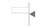
- The inclination of the saw blade against the plane of the vise is 7 degrees. This ensures higher performance when cutting profiles and bundles and at the same time increases the life of the saw blade
- The saw has a guide on the drive side mounted on a fixed beam. On the tensioning side, the guide is mounted on a sliding beam.
- Blade guide beam adjustable over the entire working range. The movement of the guide is linked to the movement of the vice clamp. It is therefore not necessary to manually adjust its position.
- The guide beam moves by means of a linear guide (2 rails, 3 trolleys) with high load capacity.
- A new way of mounting the guides - a solution with a regulated spacer.
- The space between the saw blade guide and the pulley is provided with a cover to protect the operator from the moving saw blade. The covers also protect the surrounding area from falling chips and cooling emulsion.
- The saw is equipped as standard with hydraulic saw blade tensioning - allowing ideal cutting conditions to be maintained at all times. The tensioning force is provided by 2 hydraulic cylinders.
- Automatic Indication of correct saw blade tension by means of a pressure sensor.
- Cleaning brush driven by electromotor ensures perfect cleaning of the saw blade.
- Cooling system for cutting emulsion, fed into the blade guides and directly into the cutting channel using the flexible LocLine system.
- Robust base with chip tray. The base is designed for handling the saw with a crane
- Microswitches for opening pulley covers.
- Hydraulic unit located outside the base - better cooling and access. The hydraulic unit controls the functions of the saw: opening and closing the main vice and feeder vice, tensioning the belt. The hydraulic oil pump is located outside the oil tank.
- Cover bodywork that covers the movements of the rear of the arm. The body minimises the risk of injury and contamination of the saw's surroundings with chips and cutting emulsion.
- Chip rinsing pistol
- LED strip for work area lighting.
Basic equipment of the machine:
- Saw blade
- Tool set for routine machine maintenance.
- Operating instructions in electronic form on CD.
| Code | Description | Type | |
|---|---|---|---|
| SIEMENS HMI 7" | Controling system SIEMENS with display 7". | ST | |
| 440-HMI+FK | HMI = colour control touch screen. FK=foil keyboard with basic movements | ST | |
| PCP | One year subscription for external machine programming (for Siemens control system) using www server. | O | |
| BLUEBOX | Router for remote saw service. | O | |
| 440-OPS | Protective cover for control panel. Hinged plate made of thin sheet metal. | O | |
| 440-OPE | Control panel on a freestanding external console. | OP | |
 | 440-F | Motor and frequency inverter for a fluent change of the blade speed. | ST |
| 440-DRIVE | Motor (4,0 kW) + bevel gearbox | ST | |
| 440-HM-DRIVE | More powerfull motor (5,5 kW) + bevel gearbox optimal for full use of the carbide (HM) saw blade. Calculated as assesories | OP | |
 | 440-C-WRS | Reinforcement of wheel mounting. The tensioner wheel shaft is reinforced with an additional hydraulic cylinder, the drive wheel shaft is reinforced with a bearing and a beam mounted to the frame. | ST |
 | 440-NPH-2 | Hydraulic band tension with two hydraulic cylinders located on both sides of blade tension wheel. | ST |
 | 440-BCA-7 | Slope of the saw blade (frame) 7 degrees. Optimal solution for cutting profiles and bundles, neutral solution for cutting solid bars. | ST |
 | 440-IRP | Down shift speed indication value on the display of control system ( mm/min ) | ST |
| 440-BSB SERVO | Movement of bow by linear guides, ball screw and servo motor. | ST | |
| 440-BSF SERVO | Movement of feeder by linear guides, ball screw and servo motor. | ST | |
| PEGAS ASR+ARP+RZP+ARN | ASR = Automatic cutting feed regulation based on set parameters. | ST | |
| 440-KKR | Blade deviation monitor. | OP | |
| 440-CDC | Basic library with cutting parameters, operator inputs the material informations (dimensions, type, quality) Automatical setting of cutting parameters. Operator set only information about quality and dimension of material. | ST | |
| 440-IMB | Indication of saw blade movement. If the saw blade jams, the drive pulley rotates and the tensioner pulley stands. The function protects the saw blade by stopping the arm from moving into the cut | OP | |
| 440-HPV | Solution of moving guides of band together with jaws of the vice. | ST | |
| 440-C-ECK | Cleaning brush of blade driven actively by motor.Belt drive, 790 RPM. | ST | |
| LED | Lighting of workink space. | ST | |
| 440-C-RTS-A | vice pressure regulation. Set of 2 pieces for feeder and main vice. | ST | |
| 440-C-OCP | Rebounding jaw of the vice of feeder operated by a short stroke hydraulic cylinder. Equipped by 2 rails and 4 linear trucks. Ensures contactless reverse movement of the feeder | OP | |
| 440-C-ATB | Automatic material feed precisely into the cutting zone. | ST | |
| 440-C-VTT | Universal pusher chip ejector without centre tube, included 1 Pc of BOX-TRI | ST | |
| 440-C-VTT-D | Optional chip conveyor for transportation of chips. Available only together with 440-C-VTT. | OP | |
| 440-BOX-T1 | Professional chips tipping container | OP | |
| 440-LHS | Signaling beacon - display of operating states of the saw by means of 3 colour ed lights | OP | |
| 440-C-LSG | Optical protection fence that protects the machine operator from dangerous movements of the saw components in the automatic cycle. | OP | |
| 440-C-LSG-Z | LSG-Z is an optical protective fence placed behind the saw. | OP | |
| 440-C-HP-A | Hydraulically upper clamping, 2 sets for automatic machine.Long stroke hydraulic cylinder, 2 rails and 4 linear guide carriages, clamping jaw width = max. stroke of main vise. Control via push button on control panel. Collision-free movement of the jaw, no need for mechanical intervention of the operator. | OP | |
| SYNC-2 | Synchronisation of the saw feeder movement with the roller rotation of the RDM powered conveyor in the automatic cycle. Additionally, it is possible to move the feeder synchronously with the vice clamp closed and the RDM track rollers even with manual operation | OP | |
 | SRZ-Z-500 | Additional vice mounted on the standard RDT roller track. Long stroke jaw (stroke 500mm) operated by hydraulic cylinder. The jaw control is coupled to the jaw of the main saw vice. | OP |
| MINI LUBE 34 | Mist spray lubricating system. - 2 pumps, for 34 mm blade. Replaces emulsion cooling. The system is suitable to cut profiles and pipes. 6 bar of pressurized air is neccesary for operation. | OP | |
| 440-C-QPARTS | Set of wear and tear spare parts : | O | |
| 440-C-SET M42 | Set of 10 blades in SPECTRA M42 quality – customer chooses blade's TPI. Blade specs: 5360x34x1,1 | O | |
| 440-C-SET M51 | Set of 10 blades in DURATEC M51 quality – customer chooses blade's TPI. Blade specs: 5360x34x1,1 | O | |
 | 440-C-NAV | Instruction Manual – printed version. | OP |
| 440-C-TCT | Sheet metal transport device for moving and fixing the machine in the container. Transport container tool | O | |
| RDT 1000/520 | Robust roller conveyor with coolant gutter. Width of cylinders 520 mm, length 1000 mm, 3 rollers, it is possible to put them for RDP or RDZ, load capacity 2100 kg/m. | O | |
| RDT 2000/520 | Robust roller conveyor with coolant gutter. Length 2000 mm, width of cylinders 520 mm, 5 rollers, load capacity 2100 kg/m. | O | |
| RDM 2000/520 | Input or output robust roller conveyor with driven rollers. Driving by electrical engine, worm gearbox and inverter. By chain are driving cylinders. Width of cylinders 520 mm, length 2000 mm, capacity 2100 kg/m. For automatic CNC saws can only be used with SYNC-1 accessories | OP | |
| RDML 2000/520 | Input or output robust roller conveyor with driven rollers. Driving from RDM throught chain. (RDM-L does not work without RDM conveyor). Width of cylinders 520 mm, length 2000 mm, Load capacity 2100 kg/m. | OP | |
| 440-C-RBR | Side support fixed cylinder with robust bracket, height 280 mm, diameter 67 mm including support - length 520 mm, mounted to the conveyor RDT. Impossible to install on VD roller conveyors. | O | |
| 440-C-RBRS | Side movable cylinder with robust bracket, height 280 mm, diameter 67 mm it is available only with RB. IMPOSSIBLE ASSEMBLE ON VD ROLLERTABLES. | O | |
| VZM-520 | Hydraulic operated lifting motorized cylinder, width 520 mm.VZM is designed to lift the material using hydraulic short-stroke cylinder above the level of other rollers on the conveyor. After lifting the VZM can move the material forwards or backwards by electric motor. VZM is installed instead of 2 original passive cylinders. VZM is operated independently with own control panel. VZM works only with RDT. | O | |
| 360-RDH | Independent movable cylinder, adjustable height, capacity 700 kg. INPOSIBLE ASSAMBLE ON VD1 ROLLERTABLES. | O | |
| 360-V | Roller of roller table RDT put into gap. | O | |
| 360-OZP | Mechanical fixed stop with ruler and scale line. Works only with OZP-L. Impossible use for CNC !!! IMPOSSIBLE ASSEMBLE ON VD1 ROLLERTABLES. POSSIBLE ONLY WITH ROLLER TABLE TYPE RDT/TDT | O | |
| 360-OZP-D | Mechanical fixed stop with digital display of setting length. Impossible use for CNC !!! Works only with OZD-L. IMPOSSIBLE ASSEMBLE ON VD1 ROLLERTABLES. POSSIBLE ONLY WITH ROLLER TABLE TYPE RDT/TDT. | O | |
| 360-OZS | Electromechanical stop working with RDM roller table. It has two contacts. When material switches the first contact, RDM slows down, after switching the second contact, RDM stops. Works only with OZS-L. | O | |
| 360-OZS-D | Electromechanical stop working with RDM roller table. It has two contacts. When material switches on the first contact, RDM slows down, after switching on the second contact, RDM stops. Works only with OZSD-L. | O | |
| 360-OZP-L 1000 | Measuring system for OZP mounted on 1 m roller table. | O | |
| 360-OZP-L 2000 | Measuring system for OZP mounted on 2 m roller table. | O | |
| 360-OZP-LE 1000 | Measuring system for OZP mounted on LAST 1 m roller table in the setup. | O | |
| 360-OZP-LE 2000 | Measuring system for OZP mounted on LAST 2m roller table in the setup. | O | |
| 360-OZD-L 1000 | Measuring system for OZD mounted on 1 m roller table. | O | |
| 360-OZD-L 2000 | Measuring system for OZD mounted on 2 m roller table. | O | |
| 360-OZD-LE 1000 | Measuring system for OZD mounted on LAST 1 m roller table in the setup | O | |
| 360-OZD-LE 2000 | Measuring system for OZD mounted on LAST 2 m roller table in the setup. | O | |
| 360-OZS-L 1000 | Measuring system for OZS mounted on 1 m roller table. | O | |
| 360-OZS-L 2000 | Measuring system for OZS mounted on 2 m roller table. | O | |
| 360-OZS-LE 1000 | Measuring system for OZS mounted on LAST 1 m roller table in the setup. | O | |
| 360-OZS-LE 2000 | Measuring system for OZS mounted on LAST 2 m roller table in the setup. | O | |
| 360-OZSD-L 1000 | Measuring system for OZS-D mounted on 1 m roller table. | O | |
| 360-OZSD-L 2000 | Measuring system for OZS-D mounted on 2 m roller table. | O | |
| 360-OZSD-LE 1000 | Measuring system for OZS-D mounted on LAST 1 m roller table in the setup. | O | |
| 360-OZSD-LE 2000 | Measuring system for OZS-D mounted on LAST 2 m roller table in the setup. | O |
Tech. data NO241 are valid on 1.1.2024. Producer has the right to make changes of technical data.
Values contained on this page are only for information purposes. This information is not an offer and is not a public promise. This indicative offer does not give right to close a contract. The only guiding document for the contract is a valid price list.
or send inquiry!