


 400x400 HERKULES X / Herkules
 It's no longer on sale
| mm | 0° | 45° | 60° | -45° | -60° |  |
 |
|---|---|---|---|---|---|---|---|
 |
400 | x | x | x | x | x | x |
 |
400 | x | x | x | x | x | x |
 |
400x400 | x | x | x | x | 400x250 |
 |
 |
 |
 |
 |
|---|---|---|---|---|
| 3x400V | 4,0 | 20-100 | 5580x41x1,3 | 2670 |
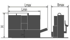
| Lmin | Lmax | Bmin | Bmax | Hmin | Hmax | V |
|---|---|---|---|---|---|---|
| 2950 | 2950 | 1450 | 1450 | 2200 | 2200 | 800 |
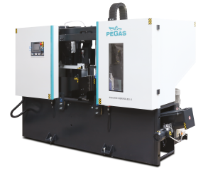
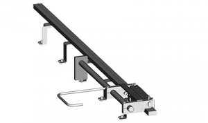
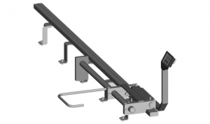
Highly productive semi-automatic, hydraulically manipulated two column band saw machine. The machine is designed for vertical cuts. It is suitable for serial production in industrial premises. Thank to its robust construction enables to cut wide range of materials including stainless stells and tool steels both profiles and full materials.
Control systém:
Machine is equipped with programmable PLC SIEMENS SIMATIC S7-1200. Blade drive, bow movements and feeder movements are controled by SIEMENS technology.
The coloured touch screen HMI SIEMENS TP 700 COMFORT enables easy communication with an operator. It shows working conditions (blade speed, moving to the cut, cutting parameters etc.)
The machine enables to work with two modes:
SEMIAUTOMATIC CYCLE: The machine cuts the material immediatelly in a semiautomatic mode. The operator uses the feeder of the machine for the manipulation with the material and for the exact feed of the material into the cutting zone. The movement of the feeder is realized by manual buttons or by GTO function. After starting GTO function the operator sets the position of the feeder, presses START button and feeder goes to the set position.
AUTOMATIC CYCLE: the feeder feeds the material according to the set programm. The operator sets the cutting programm, machine realizes these programms, it is possible to make thousand different programms.The part of one programm is a complete setting of the cut: blade speed, feed speed, setting of an automatic regulation, setting of the hight of the bar to be cut, setting of the lenght of the bar, angles values and number of pieces. The lenght and number of pieces it is possible to set in 20 lines, the machine feeds differently set lenghts automatically. Control system shows the feasibility of the cutting by the drawings
Regulation of cutting feed is realized by controlled systém by the servo-motor and throttle valve hydraulics. Then is reached very precise cutting feed. Operator will input into program requiered cutting feed (mm/min) and bandsaw this cutting feed precisely set. Two basic regimes of automatic system regulation (ASR): ARP a RZP-2.
RZP= System allows to set the optimal cutting feed rate depending on material band position. Cutting feed rate is regulated on begining and end of cut. It is suitable for using of carbide blades.
ARP = System of the automatic regulation of the cutting feed rate depending on the cutting resistance of the material or blunting the blade.
Systém offers two basic modes of ARP: BIMETAL and CARBIDE.
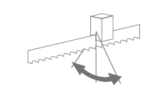
BIMETAL mode is suitable for optimalization of the cutting feed when cutting profiles by bimetal blades. The cutting feed is higher if the blade cuts sides of the profile. As the blade reaches the full material, the system reduces the cutting feed automatically so that teeth gap of the blade would not be filled.
CARBIDE mode is suitable for cutting of full bars. If the blade is excessive loaded is the cutting feed reduced on 50 % and cut is finished by this speed.
The control panel is placed in the tightening pulley cover. It is equipped with safety button, next buttons are for machine start and stop and other setting.
Cutting feed rate is regulated by hydraulic throttle valve leaded by servomotor enabling very precise feed rate. The operator sets in the program needed feed rate (mm/min) and the machine will set it up. In this way there are no external factors influencing cutting feed like temperature (viscosity) of hydraulic oil.
Construction:
The machine is constructionaly designed in that way, so that it corresponds to extreme exertions in productive conditions. Massive construction enables using of carbid blades comfortably.
The arm of machine with columns situated as near the clamping vice as possible minimizes vibrations and enables max. cutting performance.
The arm of the machine is robust, heavy weldment and it is designed so that a toughtness and a precision of cut was ensured.
The arm moves along two columns using a four row linear leading with a high loading capacity. Arm movement using two hydraulic cylinders.
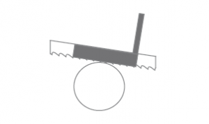
The robust steel pulleys sloped of 25 degrees regarding the level of the cut. Thanks to sloped arm the twist of the blade is eliminated and these is possibility to bring the blade closer to the minimal distance from the linear leading on columns. This arrangement eliminates vibrations and enables the max. cutting performance of the machine.
Upper position automatically using Pegas DPP system (touching lath placed closely below tooth of blade: T-bar, linear leading, microswitch, adjusting screw) or using of incremental sensor for measuring of a position above material. Upper cutting position of frame is detected automaticaly using control system after setting of the size parameters of cutted material.
Down position using adjusting stop and microswitch. After reaching of bottom position arm goes to upper position automatically.
Main vice with divided jaw that clamps the material in front of as well as behind the cut. The jaws allow a safe grip.The optimalization of the chip movement through the fixed jaw directly to the chip extractor.
Jaws of the main vice move on two rails of linear leading using hydraulic cylinder. One jaw is longstroke (the movement by longstroke hydraulic cylinder), one is fixed.
Regulation valves for setting a vice pressure in hydraulic system.
Basic equipment of machine:
The blade leading in guides with hardmetal plates and leading bearings and along cast iron pulleys.
There is a guide situated on the firm beam on the drive side. On the tightening side there is the guide situated on the moving beam.
The guide beams of the blade are adjustable in the whole working range. A giude moving is connected with a vice-jaw movement so that to achieve the minimum distance of the guide and material. That is why it is not neccessary to set the position manually.
The guide beam of the blade is placed in linear rails (2 linear rails and 4 bearings) with high bearing capacity.
The saw-band is equipped with a guard, which protects the operator from millings and cutting emulsion.
Machine has hydraulic band tightening.
Automatic indication of blade tension.
A cleaning brush is driven by an electroengine and ensures perfect cleaning of a blade.
There is a planet gear box drive and a three-phase electroengine, a fluent regulation of a blade speed by a frequency converter for a fluent change of blade speed.
The cooling system for emulsion, leaded to the guides of the blade and by LocLine system directly to the cut groove.
Massive base with a tank for chips and with chip extractors.Base is designed for manipulation manipulation with machine by pallet truck and also by any hight lift truck.
Indication of blade tightening and opening of the cover.
Controlling 24 V.
Maschine is equipped with hydraulic system which controles all functions of that maschine. It pushes the arm to cut, pulls up the arm and opens and closes vices.
Basic equipment of machine:
Chip extractor
Lighting of workink space.
Band saw blade.
Set of spanners for common service.
Manual instructions in eletronic form (CD).
Operating cycle:
After starting the machine, vices are clamped automatically, cut is made by selected cutting speed, in the end position microswitch is on, arm goes to selected upper position and vices open automatically. The operator only handles material.
| Code | Description | Type | |
|---|---|---|---|
| F | Motor and frequency converter for a fluent change of the circumferential speed of the blade. | ST | |
| SIEMENS HMI 7" | Controling system SIEMENS with display 7". | ST | |
| PCP | One year subscription for external machine programming (for Siemens control system) using www server. | O | |
| BLUEBOX | Router for remote saw service. | O | |
| CDC | Basic library with cutting parameters, operator inputs the material informations (dimensions, type, quality) Automatical setting of cutting parameters. Operator set only information about quality and dimension of material. | ST | |
| LED | Lighting of workink space. | ST | |
| NPH | Hydraulic tension of band. | ST | |
| HPV | Solution of moving guides of band together with jaws of the vice. | ST | |
 | 400-DPP | Automatic end stop of the upper position. | ST |
| PEGAS ASR | ASR = Automatic cutting feed regulation based on set parameters. | ST | |
| RTS | Regulation press of vice. | ST | |
| ECK | Cleaning brush of blade driven actively by motor. | ST | |
 | 400-KKR | Check of cut perpendicularity. | OP |
| BOX-PCS | Box for cutted pieces with emulsion draining to the waterproof tank. | O | |
| BOX-TRI | Box for the chips with emulsion draining to the waterproof tank. | O | |
| BOX-TAH | Tool for manipulation with BOX-PCS and BOX-TRI. | O | |
| 400-HPR | Hydraulic upper clamping. Jaw clamps material in vertical direction using hydraulic cylinder and two axis of linear leading. | OP | |
| MINI LUBE 41 | Wasteless lubricating system – 2 pumps, for blade 41 mm. Instead of emulsion cooling, specially for cutting profiles and non-ferrous metals, necessary supply of pressed air 6 Atm. | OP | |
| LASER LINE | Laser indicator of cut position. | OP | |
| 400x400-OPO | Control panel positioned on the right side of front cover. | OP | |
| 400-QPARTS | Set of easy worn away spare parts : | O | |
| 400x400-SET M42 | Set of 10 blades in M42 quality – with customer’s choice of teeth. 5580x41x1,3 | O | |
| 400x400-SET M51/10 | Set of 10 blades in M51 quality – with customer’s choice of teeth. 5580x41x1,3 | O | |
 | 400–NAV | Manual instruction – printed version. | O |
| 400x400 TPF-1 | Frame for preparation of the material. It serves as additional side frame to roller tables to prepare tube material before the cutting on saw. Load capacity:7000kg | OP | |
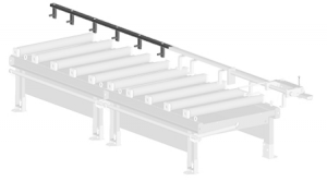
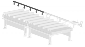
 | 400-RDP 1000/450 | Special input roller conveyor, with a gutter which prevents leakage of emulsion on the floor. Width of cylinders 450 mm, length 1000 mm, 6 rollers, capacity 1000 kg/m. | O |
 | 400-RDZ 1000/450 | Special output roller conveyor, with a gutter which prevents leakage of emulsion on the floor. Width of cylinders 450 mm, length 1000 mm, 6 rollers, capacity 1000 kg/m. | O |
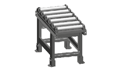
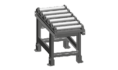
| RDT 1000/450 | Robust roller conveyor with coolant gutter. Length 1000 mm, width of cylinders 450 mm, 3 rollers, load capacity 1000 kg/m. | O | |
| RDT 2000/450 | Robust roller conveyor with coolant gutter. Length 2000 mm, width of cylinders 450 mm, 5 rollers, load capacity 1000 kg/m. | O | |
| RDM 2000/450 | Input or output robust roller conveyor with driven rollers . Driving by electric engine, vorm gearbox and converter. By chain are driving cylinders. Width of cylinders 450 mm, length 2000 mm, capacity 1000 kg/m. For automatic CNC saws can only be used with SYNC-1 accessories | OP | |
| RDML 2000/450 | Input or output robust roller conveyor with driven rollers. Driving from RDM throught chain (RDM-L does not work without RDM conveyor). Width of cylinders 450 mm, length 2000 mm. Load ccapacity 1000 kg/m. | OP | |
| VZM-450 | The cylinder of rollertable, which is driven by electroengine, width 450 mm, is able to lift the material hydraulically above the level of other rollers. Working only with RDT insta 2 Pc of original cylinders. Control of the roller is independent on the controlling of the machine, the roller has its own controlling panel. | OP | |
| RDH-450 | Independent movable cylinder, adjustable height, capacity 700 kg. Width of roller 450mm. | O | |
| 400-V | Roller of roller table RDT put into gap. | O | |
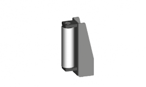 | 400-RBR | Side support fixed cylinder, height 280 mm, diameter 67 mm with its own frame, mounted to roller tables RDT. | O |
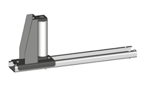 | 400-RBRS | Side adjustable roller, with its own steel frame, and with the movable leading 450 mm, fixed by 2 pcs of T-nuts. Height 280 mm, diameter 67 mm. | O |
| 400-CSV | Hydraulical shift for the RBRS roller including assambly of electrical and hydraulical instalation. Possibile only with RBRS | OP | |
 | OZP | Mechanical fixed stop with ruler and scale line 2 meters long. INPOSIBLE ASSAMBLE ON VD1 ROLLERTABLES. | O |
 | OZP-D | Mechanical fixed stop with digital display 2 meters long. INPOSIBLE ASSAMBLE ON VD1 ROLLERTABLES. | O |
 | OZS | Electromechanical stop working with RDM roller table. It has two contacts. When material switches the first contact, RDM slows down, after switching the second contact, RDM stops. Works only with OZS-L. | O |
 | OZS-D | Electromechanical stop working with RDM roller table. It has two contacts. When material switches on the first contact, RDM slows down, after switching on the second contact, RDM stops. | O |
| OZP-L-RDZ | Measuring system rail for OZP mounted on FIRST roller table. | O | |
| OZP-LE-RDZ | Measuring system rail for OZP mounted on FIRST AND EITHER LAST roller table. | O | |
| OZD-L-RDZ | Measuring system for OZD mounted on FIRST roller table. | O | |
| OZD-LE-RDZ | Measuring system for OZD mounted on FIRST AND EITHER LAST roller table. | O | |
| OZS-L-RDZ | Measuring system for OZS mounted on FIRST roller table. | O | |
| OZS-LE-RDZ | Measuring system for OZS mounted on FIRST AND EITHER LAST roller table. | O | |
| OZSD-L-RDZ | Measuring system for OZS-D mounted on FIRST roller table. | O | |
| OZSD-LE-RDZ | Measuring system for OZS-D mounted on FIRST AND EITHER LAST roller table. | O | |
| OZP-L 1000 | Measuring system rail for OZP mounted on 1 m roller table. | O | |
 | OZP-L 2000 | 2 meters long extension of OZP. | O |
| OZP-LE 1000 | Measuring system rail for OZP mounted on LAST 1 m roller table in the setup. | O | |
| OZP-LE 2000 | Measuring system rail for OZP mounted on LAST 2m roller table in the setup. | O | |
| OZD-L 1000 | Measuring system for OZD mounted on 1 m roller table. | O | |
 | OZD-L 2000 | 2 meters long extension of OZD. | O |
| OZD-LE 1000 | Measuring system for OZD mounted on LAST 1 m roller table in the setup. | O | |
| OZD-LE 2000 | Measuring system for OZD mounted on LAST 2 m roller table in the setup. | O | |
| OZS-L 1000 | Measuring system for OZS mounted on 1 m roller table. | O | |
| OZS-L 2000 | Measuring system for OZS mounted on 2 m roller table. | O | |
| OZS-LE 1000 | Measuring system for OZS mounted on LAST 1 m roller table in the setup. | O | |
| OZS-LE 2000 | Measuring system for OZS mounted on LAST 2 m roller table in the setup. | O | |
| OZSD-L 1000 | Measuring system for OZS-D mounted on 1 m roller table. | O | |
| OZSD-L 2000 | Measuring system for OZS-D mounted on 2 m roller table. | O | |
| OZSD-LE 1000 | Measuring system for OZS-D mounted on LAST 1 m roller table in the setup. | O | |
| OZSD-LE 2000 | Measuring system for OZS-D mounted on LAST 2 m roller table in the setup. | O |
Tech. data NO241 are valid on 1.1.2024. Producer has the right to make changes of technical data.
Values contained on this page are only for information purposes. This information is not an offer and is not a public promise. This indicative offer does not give right to close a contract. The only guiding document for the contract is a valid price list.