


 DC-540SA-X / CALIBER

| mm | 0° | 45° | 60° | -45° | -60° |  |
 |
|---|---|---|---|---|---|---|---|
 |
550 | x | x | x | x | ||
 |
550x500 | x | x | x | x | 550x460 |
 |
 |
 |
 |
 |
|---|---|---|---|---|
| 3x400V | 5,5 | 15-150 | 6200x41x1,3 | 3325 |
| Lmin | Lmax | Bmin | Bmax | Hmin | Hmax | V |
|---|---|---|---|---|---|---|
| 3250 | 3840 | 1945 | 1945 | 2425 | 2422 | 800 |
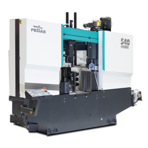
- It is a highly efficient semi-automatic,band-saw.
- The machine is designed for vertical
- It is suitable for serial production in industrial premises. Due to its robust construction, enables the cutting of a wide range of material qualities, including stainless steels and tool steels.
- The saw is designed for cutting straight bars of steel material.
Control system:
- Machine is equiped with programmable PLC SIEMENS SIMATIC S7-1500. The saw blade drive and arm movement are completely controlled and drive by SIEMENS technology.
- The coloured touch screen HMI SIEMENS TP 700 COMFORT enables easy communication with an operator. It shows working conditions (blade speed, moving to the cut, cutting parameters etc.)
- Display size 7´ (93mm x 153mm)
- The machine works in semiautomatic mode.
- Cutting feed rate is regulated by control system by means of the servodriver, servomotor, ball screw and preloaded nut located on the saw arm. This achieves a very precise cutting feed. The operator sets in the program needed feed rate (mm/min) and the machine will set it up.
- Two basic regimes of automatic system regulation (ASR): ARP a RZP.
- RZP = Zone regulation. System enable to cut material in 5 zones, because of setting optional cutting feed and blade speed according on blade position..
- ARP = System of the automatic regulation of the cutting feed rate depending on the cutting resistance of the material or blunting the blade. Systém offers two basic modes of ARP: BIMETAL and CARBIDE.
- The control panel is located on the console in a safe position. The control panel includes a digital display of the saw control system and a high quality foil keypad. The keypad is used to control the basic movements of the saw (movement of the arm and vice) and to start the saw's working cycle. The control panel is also equipped with a safety button to stop the saw.
- Safety module with autodiagnostics.
- 24V control
Construction:
- The saw is designed to fully support the efficient use of carbide saw blades. The band saw has a robust design to withstand extreme stresses in production conditions. All machine components are designed and optimized to minimize vibrations and allow maximum cutting performance of the machine.
- Saw blade speed range 15 – 150 m/min
- The saw arm moves from top to bottom via 2 linear guide rails with 4 carriages with preloaded ball bearings. The linear guide is mounted on robust columns.
- The arm is a robust weldment and is designed to ensure the necessary rigidity and cutting accuracy
- Movement of frame by linear guideway, sharpen ball screw, preloaded nut, flexible clutch, worm gear and servo-drive.
- The saw blade is guided on robust cast iron pulleys.
- WRS - Reinforcement of pulley mounting - drive pulley mounted directly on the output shaft of the gearbox. The pulley is supported on both sides by a bearing seat =minimizing the load on the shaft seat. The tension pulley is held/tensioned by two hydraulic cylinders at both ends of the centre pin =significant reduction of stress and extension of the life of the bearing. The tension pulley mounting is with zero play=conical bearings secured by KM nut.
- Frame using measuring system for evaluate frame position over material. The upper and lower working position of the arm is set by entering a value into the saw control system
- Bandsaw use for identify position absolute rotational encoder= Isn´t requirement to reference position when machine is switched on.
- Movement of the clamp of the main vise by rail in linear guides by means of a long-stroke hydraulic cylinder. The long-stroke jaw ensures full stroke = clamping of even very small rods. The second jaw is solid..
- Control valve for vise pressure adjustment, pressure indication on pressure gauge
- There is a roller conveyer which supports material in whole feeded lenght.
- The saw blade is driven by a bevel gearbox, asynchronous motor and frequency inverter.
- External fan cooling of the saw blade drive.
- Thermal protection of the electric motor
- Belt guidance in guides with plates and guide bearings and on cast iron pulleys and in the upper part (reverse) the belt is supported by a vibration damper
- The inclination of the saw blade against the plane of the vise is 7 degrees. This ensures higher performance when cutting profiles and bundles and at the same time increases the life of the saw blade
- The saw has a guide on the drive side mounted on a fixed beam. On the tensioning side, the guide is mounted on a sliding beam.
- Blade guide beam adjustable over the entire working range. The movement of the guide is linked to the movement of the vice clamp. It is therefore not necessary to manually adjust its position.
- The guide beam moves by means of a linear guide (2 rails, 3 trolleys) with high load capacity.
- A new way of mounting the guides - a solution with a regulated spacer.
- BGT-S - mechanical pressure of the saw blade in the guides by means of disc springs
- The space between the saw blade guide and the pulley is provided with a cover to protect the operator from the moving saw blade. The covers also protect the surrounding area from falling chips and cooling emulsion.
- The saw is equipped as standard with hydraulic saw blade tensioning - allowing ideal cutting conditions to be maintained at all times. The tensioning force is provided by 2 hydraulic cylinders.
- Automatic Indication of correct saw blade tension by means of a pressure sensor.
- Cleaning brush driven by electromotor ensures perfect cleaning of the saw blade.
- Cooling system for cutting emulsion, fed into the blade guides and directly into the cutting channel using the flexible LocLine system.
- Robust base with chip tray. The base is designed for handling the saw with a crane
- Microswitches for opening pulley covers.
- Hydraulic unit located outside the base - better cooling and access. The hydraulic unit controls the functions of the saw: opening and closing the main vice, tensioning the belt. The hydraulic oil pump is located outside the oil tank.
- Cover bodywork that covers the movements of the rear of the arm. The body minimises the risk of injury and contamination of the saw's surroundings with chips and cutting emulsion.
- Chip rinsing pistol
- LED strip for work area lighting.
Basic equipment of the machine:
- Saw blade
- Tool set for routine machine maintenance.
- Operating instructions in electronic form on CD.
| Code | Description | Type | |
|---|---|---|---|
| SIEMENS HMI 7" | Controling system SIEMENS with display 7". | ST | |
| 540-HMI+FK | HMI = colour control touch screen. FK=foil keyboard with basic movements | ST | |
| ZAPSI | Industry 4.0, Connection to bandsaw monitoring and evaluation of machine efficiency, operation, production, and energy consumption. | OP | |
| PCP | One year subscription for external machine programming (for Siemens control system) using www server. | O | |
| BLUEBOX | Router for remote saw service. | OP | |
| 540-OPS | Protective cover for control panel. Hinged plate made of thin sheet metal. | O | |
| 540-OPE | Control panel on a freestanding external console. | OP | |
| F | Motor and frequency converter for a fluent change of the circumferential speed of the blade. | ST | |
| 540-DRIVE | Motor (5,5 kW) + bevel gearbox | ST | |
| 540-HM-DRIVE | More powerfull motor (7,5 kW) + bevel gearbox optimal for full use of the carbide (HM) saw blade. Calculated as assesories | OP | |
| WRS | Reinforcement of wheel mounting. The tensioner wheel shaft is reinforced with an additional hydraulic cylinder, the drive wheel shaft is reinforced with a bearing and a beam mounted to the frame. | ST | |
| NPH-2 | Hydraulic band tension with two hydraulic cylinders located on both sides of blade tension wheel. | ST | |
| BCA-7 | Slope of the saw blade (frame) 7 degrees. Optimal solution for cutting profiles and bundles, neutral solution for cutting solid bars. | ST | |
| IRP | Down shift speed indication value on the display of control system ( mm/min ) | ST | |
| 540-BSB SERVO | Movement of bow by linear guides, ball screw and servo motor. | ST | |
| PEGAS ASR | ASR = Automatic cutting feed regulation based on set parameters. | ST | |
| 540-KKR | Blade deviation monitor. | OP | |
| 540-ABP | Automatic contactless arm working position adjustment using an optical sensor | OP | |
| CDC | Basic library with cutting parameters, operator inputs the material informations (dimensions, type, quality) Automatical setting of cutting parameters. Operator set only information about quality and dimension of material. | ST | |
| 540-IMB | Indication of saw blade movement. If the saw blade jams, the drive pulley rotates and the tensioner pulley stands. The function protects the saw blade by stopping the arm from moving into the cut | OP | |
| HPV | Solution of moving guides of band together with jaws of the vice. | ST | |
| ECK | Cleaning brush of blade driven actively by motor. | ST | |
| LED | Lighting of workink space. | ST | |
| RTS | Regulation press of vice. | ST | |
| 540-C-OCS | Hydraulic operated, short-stroke retracting clamp of fixed main vice. Equipped by 1 rail and 2 linear trucks. | OP | |
| 540-C-PUS | Prismatic clamps for cutting hexagonal tube bundles. Manual adjustment of the upper jaw for bundle size adjustment. This is a set of 1 clamp for fixed jaw and 1 clamp for movable jaw vice. | O | |
| 540-GPZ 500 | Support table on the output side of the machine. Length 500mm. Horizontal stainless steel surface. Movement of cutting emulsion back into the machine, Connection with roller conveyors RDT / RDM. | O | |
| 540-C-VTT | Universal pusher chip ejector without centre tube, included 1 Pc of BOX-TRI | OP | |
| 540-C-VTT-D | Optional chip conveyor for transportation of chips. Available only together with 540-VTT. | OP | |
| 540-C-HP | Top pressure for semi-automatic. Long stroke hydraulic cylinder, 2 rails and 4 linear guides, clamping jaw width = max. stroke of main vise. Control via push button on control panel. Collision-free movement of the jaw, no need for mechanical intervention of the operator. | OP | |
| 540-SRZ+2OCS+HP | vice behind the cut equipped with a recoiling jaw and a long-stroke nesting clamp. For proper function, it is also necessary to mount the recoiling jaw on the main vice. | OP | |
| SRZ-Z-500 | Additional vice mounted on the standard RDT roller track. Long stroke jaw (stroke 500mm) operated by hydraulic cylinder. The jaw control is coupled to the jaw of the main saw vice. | OP | |
| MINI LUBE 41 | Wasteless lubricating system – 2 pumps, for blade 41 mm. Instead of emulsion cooling, specially for cutting profiles and non-ferrous metals, necessary supply of pressed air 6 Atm. | O | |
| LASER LINE | Laser indicator of cut position. | O | |
| 540-C-SET M42 | Set of 10 blades in SPECTRA M42 quality – customer chooses blade's TPI. Blade specs: 6200x41x1,3 | O | |
| 540-C-SET M51 | Set of 10 blades in DURATEC M51 quality – customer chooses blade's TPI. Blade specs: 6200x41x1,3 | O | |
| 540-C-NAV | Instruction Manual – printed version. | O | |
| 540-TPF 6000 | Transverse preparation frame (unpacking counter). Steel structure with 4 robust crossbars for storing bar material with a maximum length of 6000mm. Loading area 1800 mm. Total load capacity: 8000kg, max. load capacity per crossbar: 2000kg | OP | |
| VD-2000/620/89/6 | Input or output roller conveyor with a gutter which prevents leakage of emulsion on the floor. Length 2000 mm, width of cylinders 620 mm, capacity 350 kg/m. | O | |
| VD-V-620 | Aditional cylinder, lenght 620 mm. | O | |
| VD-VB-190 | Vertical cylinder 190 mm assamblen od the VD1. | O | |
| VD-BL | Support from vertical side - bearing. Assambled on VD1 | O | |
| RDT 1000/620 | Robust roller conveyor with coolant gutter. Length 1000 mm, width of cylinders 620 mm, 3 rollers, it is possible to put them for RDR or RDL, capacity 2500 kg/m. | O | |
| RDT 2000/620 | Robust roller conveyor with coolant gutter. Length 2000 mm, width of cylinders 620 mm, 5 rollers, it is possible to put them for RDR or RDL ,capacity 2500 kg/m. | O | |
| RDM 2000/620 | Input or output robust roller conveyor with driven rollers. Driving by electric engine, worm gearbox and converter. By chain are driving cylinders. Width of cylinders 620 mm, length 2000 mm, capacity 2500 kg/m. | OP | |
| RDML 2000/620 | Input or output robust roller conveyor with driven rollers. Driving from RDM throught chain. (RDM-L does not work without RDM conveyor) Width of cylinders 620 mm, length 2000 mm. Load capacity 2500 kg/m. | OP | |
| VZM-620 | The cylinder of rollertable, which is driven by electroengine, with 620 mm, is able to lift the material hydraulically above the level of other rollers. It is solution for later assembly to the standard rollertable RDT insta 2pcs of original cylinders. Control of the roller is independent on the controlling of the machine, the roller has its own controlling panel. | OP | |
| 500-RBR | Side support fixed cylinder, height 280 mm, diameter 87 mm with its own frame, mounted to roller tables RDT. | O | |
| 500-RBRS | Side adjustable roller, with its own steel frame, and with the movable leading 620 mm, fixed by 2 pcs of T-nuts. Height 280 mm, diameter 87 mm. | O | |
| V-620 | Roller of roller table RDT put into gap. | O | |
| RDH-600 | Independent movable cylinder, adjustable height, capacity 700 kg. Width of roller 600mm. | O | |
| RDT-XY1-620 | Roller table setup (with one motorised VZM-620). The setup has total Length 7500 mm. In this option is included 4 powered cross-conveyors with Length of 4000 mm. The flow of material is one way, manual control. Max. weight of material transferred per one segment: 1000 kg.To increase efficiency. For connection to the saw it is necessary to order RDR / RDL | OP | |
| LMP 1000 | Measuring stop for defining the length of the cut bar. Fixed contact with the material to be measured. Length reading with scale measuring tape. | O | |
| LMP 2000 | *Recommended for measuring lengths up to 2000mm. | O | |
| LMP 3000 | * Recommended for measuring lengths up to 3000mm. | O | |
| LMP 4000 | *Recommended for measuring lengths up to 4000mm. | O | |
| LMP 5000 | *Recommended for measuring lengths up to 5000mm. | O | |
| LMP 6000 | *Recommended for measuring lengths up to 6000mm. | O | |
| LMPD 1000 | Measuring stop for defining the length of the cut bar. Fixed contact with the measured material. The length is shown on the display. | O | |
| LMPD 2000 | *Recommended for measuring lengths up to 2000mm. | O | |
| LMPD 3000 | *Recommended for measuring lengths up to 3000mm. | O | |
| LMPD 4000 | * Recommended for measuring lengths up to 4000mm. | O | |
| LMPD 5000 | *Recommended for measuring lengths up to 5000mm. | O | |
| LMPD 6000 | *Recommended for measuring lengths up to 6000mm. | O | |
| LMS 1000 | Measuring stop for defining the length of the cut bar. Sliding soft-contact with the material to be measured. Length reading with scale measuring tape. | O | |
| LMS 2000 | *Recommend to use for measuring lengths up to 2000mm. | O | |
| LMS 3000 | *Recommend to use for measuring lengths up to 3000mm. | O | |
| LMS 4000 | *Recommend to use for measuring lengths up to 4000mm. | O | |
| LMS 5000 | *Recommend to use for measuring lengths up to 5000mm. | O | |
| LMS 6000 | *Recommend to use for measuring lengths up to 6000mm. | O | |
| LMSD 1000 | Measuring stop for defining the length of the cut bar. Sliding soft-contact with the material to be measured.The length is shown on the display. | O | |
| LMSD 2000 | *Recommend to use for measuring lengths up to 2000mm. | O | |
| LMSD 3000 | *Recommend to use for measuring lengths up to 3000mm. | O | |
| LMSD 4000 | *Recommend to use for measuring lengths up to 4000mm. | O | |
| LMSD 5000 | *Recommend to use for measuring lengths up to 5000mm. | O | |
| LMSD 6000 | *Recommend to use for measuring lengths up to 6000mm. | O |
Tech. data NO241 are valid on 1.1.2024. Producer has the right to make changes of technical data.
Values contained on this page are only for information purposes. This information is not an offer and is not a public promise. This indicative offer does not give right to close a contract. The only guiding document for the contract is a valid price list.
or send inquiry!