


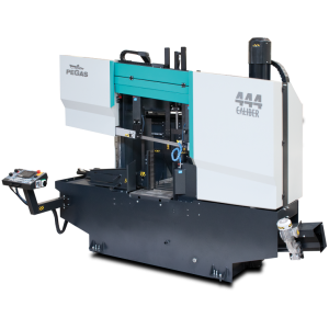
 DC-444CNC-A / CALIBER

| mm | 0° | 45° | 60° | -45° | -60° |  |
 |
|---|---|---|---|---|---|---|---|
 |
440 | x | x | x | x | ||
 |
500x400 | x | x | x | x | 500x400 |
 |
 |
 |
 |
 |
|---|---|---|---|---|
| 3 x 400V | 5,5 | 15-150 | 6200 x 41 x 1,3 | 4150 |
| Lmin | Lmax | Bmin | Bmax | Hmin | Hmax | V |
|---|---|---|---|---|---|---|
| 3700 | 4116 | 2030 | 2030 | 2390 | 2522 | 800 |
- Highly productive, automatic dual column band saw with multiple material feeding
- The saw is designed for cutting material in straight cuts
- The saw has the concept FVC = feeder – cut - main vice. The FVC concept enables cutting of single bars and bundles in an automatic cycle with short residue.
- The saw is used in serial production in industrial plants and it can cut a wide range of material grades including stainless and tool steels due its robust design.
Control system:
- The machine is equipped with programmable PLC MITSUBISHI FX5_U64. The saw blade drive and feeder movement are completely controlled by MITSUBISHI technology.
- The colour touch screen allows easy communication with the machine operator. It shows working states such as blade speed, cutting feed and the status of individual working movements.
- Display size 7' (92x153mm)
- The saw allows you to work with two modes:
- SEMI-AUTOMATIC (MANUAL) MODE: The saw immediately cuts the material in semi-automatic mode. The operator uses the saw's feeder to manipulate the material to be cut and to accurately move the material into the cut zone. The movement of the feeder is realized by manual buttons or by the GTO function. After starting the GTO function, the operator enters the position of the feeder and pressing the START GTO button moves the feeder to the entered position.
- AUTOMATIC MODE: The feeder feeds the cut blank based on the set program. The operator sets the cutting program and the saw then executes these programs. The operator can store up to 100 programs. One program includes complete cutting settings: blade speed, cutting bar height setting, bar length setting and number of cuts. The length and number can be set in 20 lines. The saw automatically feeds the different lengths entered.
- Regulation of cutting feed is realized by controlled systém by the servo-motor and throttle valve hydraulics. Then is reached very precise cutting feed. Operator will input into program requiered cutting feed (mm/min) and bandsaw this cutting feed precisely set.
- Two basic regimes of automatic system regulation (ASR): ARP a RZP-2.
- RZP-2: cutting zones regulation. System enables to set of optimal shift speed (movement to cut) and blade speed in 5 different zones depending on blade position.
- ARP = System of the automatic regulation of the cutting feed rate depending on the cutting resistance of the material or blunting the blade.
- System offers two basic modes of ARP: BIMETAL and CARBIDE.
- BIMETAL mode is suitable for optimalization of the cutting feed when cutting profiles by bimetal blades. The cutting feed is higher if the blade cuts sides of the profile. As the blade reaches the full material, the system reduces the cutting feed automatically so that teeth gap of the blade would not be filled.
- CARBIDE mode is suitable for cutting of full bars. If the blade is old (blunt), loaded is the cutting feed reduced Reaction time is slower than in mode BIMETAL.
- The control panel is located on the console in a safe position. The control panel includes a digital display of the saw control system and a high quality foil keypad. The keypad is used to control the basic movements of the saw (movement of the arm, vices and feeder) and to start the saw's working cycle. The control panel is also equipped with a safety button to stop the saw.
- Safety module with self-diagnosis.
- 24V control
Construction:
- The band saw has a robust design to withstand extreme stresses in production conditions. All machine components are designed and optimized to minimize vibrations and allow maximum cutting performance of the machine.
- Saw blade speed range 15 - 150m/min.
- The saw arm with the columns close to the clamping vice and the saw blade close to the columns minimize vibrations and allow maximum cutting performance of the machine.
- The arm is a robust weldment and is designed to ensure the necessary rigidity and cutting accuracy
- The arm moves on two columns using a four-row linear guide with a high load capacity.
- Arm movement by hydraulic cylinder
- The saw blade is guided on robust cast iron pulleys.
- WRS - Reinforcement of pulley mounting - drive pulley mounted directly on the output shaft of the gearbox. The pulley is supported on both sides by a bearing seat =minimizing the load on the shaft seat. The tension pulley is held/tensioned by two hydraulic cylinders at both ends of the centre pin =significant reduction of stress and extension of the life of the bearing. The tension pulley mounting is with zero play=conical bearings secured by KM nut.
- The saw uses a sensor and magnetic tape to evaluate the position of the arm above the material. The upper and lower working position of the arm is set by entering a value into the saw control system. The lower end position can also be determined by a limit switch.
- The main vise is a robust steel weldment.
- Movement of the long stroke jaws of the main vise along two rails of the linear guide, by means of a hydraulic cylinder. The long stroke jaw ensures full stroke = clamping even very small bars. The second jaw is fixed. Accessory at extra cost is a short stroke jaw = non-contact feeding of curved material. The short stroke jaw is mounted on a linear guide. The stroke of the short stroke roller is 15 mm
- Control valve for vise pressure adjustment, pressure indication on pressure gauge
- Feeder movement by linear guide, ball screw, preloaded nut, toothed belt transmission and asynchronous motor.
- Precise positioning of the feeder is solved automatically by the Mitsubishi frequency inverter. An incremental rotary encoder to indicate the position of the feeder. When stopped, the motor is fixed by a brake.
- Material indication in the feeder: an optical sensor indicates that there is material in the feeder. If there is no material in the feeder, the saw finishes feeding the rest of the bar and waits for the next bar to be inserted.
- A roller conveyor supporting the fed material along its entire length passes through the saw.
- The feeding vise is a robust steel weldment. The jaws ensure secure clamping of the material.
- Movement of the jaws of the feeding vise along two rails of the linear guideway, using hydraulic cylinders. One jaw is long stroke hydraulic cylinder. The other jaw is short stroke. Short-stroke jaw = non-contact reverse motion of the feeder. Advantage when feeding crooked material.
- GTO function (go to position).
- The saw allows two basic feeding modes:
- o NORMAL: the feeder moves between the zero position and the position of the specified feed length.
- o INCREMENTAL: the feeder moves to the limit position, clamps the bar and feeds it sequentially into the cut.
- Feeder movement modes:
- o CONTINUAL: optimal for cutting longer bars
- o STEP BY STEP: requires cooperation with the machine operator when taking short pieces. Each step of the program must be confirmed by the machine operator
- CMU mode: opening of the cutting zone on the feeder side for non-contact movement of the saw blade to the upper position. It is used especially when using carbide blades
- Saw blade drive via bevel gearbox and three-phase electric motor with variable blade speed control by frequency inverter
- External fan cooling of the saw blade drive.
- Thermal protection of the electric motor.
- The blade is guided in guides with carbide plates, bearings, then on cast iron pulleys and in the upper part (reverse) the blade is supported by vibration dampers.
- The inclination of the saw blade against the plane of the vise is 7 degrees. This ensures higher performance when cutting profiles and bundles and at the same time increases the life of the saw blade.
- The saw has a guide on the drive side mounted on a fixed beam. On the tensioning side, the guide is mounted on a sliding beam.
- Blade guide beam adjustable over the entire working range. The movement of the guide is linked to the movement of the vice clamp. It is therefore not necessary to manually adjust its position.
- The guide beam moves by means of a linear guide (2 rails, 3 trolleys) with high load capacity.
- A new way of mounting the guides - a solution with a regulated spacer.
- BGT-S - mechanical pressure of the saw blade in the guides by means of disc springs
- The space between the saw blade guide and the pulley is provided with a cover to protect the operator from the moving saw blade. The covers also protect the surrounding area from falling chips and cooling emulsion.
- The saw is equipped as standard with hydraulic saw blade tensioning - allowing ideal cutting conditions to be maintained at all times. The tensioning force is provided by 2 hydraulic cylinders.
- Automatic Indication of correct saw blade tension by means of a pressure sensor.
- The electric motor-driven brush ensures perfect cleaning of the saw blade.
- Robust base with chip tray and chip extractor. The base is adapted for handling the saw with a crane.
- Cooling system for cutting emulsion, fed into the blade guides and directly into the cutting channel using the flexible LocLine system.
- Microswitches for opening pulley covers.
- Hydraulic unit is located outside the base - better cooling and access. The hydraulic unit controls the saw functions: arm movement, opening and closing the main and feed vise and tensioning the saw blade. The hydraulic oil pump is located outside the oil tank.
- A complete bodywork that covers the arm and feeder movements. The bodywork minimizes the risk of injury and contamination of the saw surroundings by chips and cutting emulsion.
- The chip conveyor. Type. Drive: worm gearbox + electric motor. Thermal protection against motor overheating.
- Chip rinsing pistol
- LED strip for work area lighting.
Basic equipment of the machine:
- Saw blade
- Tool set for routine machine maintenance.
- Operating instructions in electronic form on CD.
| Code | Description | Type | |
|---|---|---|---|
| MITSUBISHI | Controling system MITSUBISHI. | ST | |
| 444-HMI+FK | HMI = colour control touch screen. FK=foil keyboard with basic movements | ST | |
| 444-OPS | Protective cover for control panel. Hinged plate made of thin sheet metal. | O | |
| 444-OPE | Control panel on a freestanding external console. | OP | |
| F | Motor and frequency converter for a fluent change of the circumferential speed of the blade. | ST | |
| 444-DRIVE | Motor (5,5 kW) + bevel gearbox | ST | |
| 444-HM-DRIVE | More powerfull motor (7,5 kW) + bevel gearbox optimal for full use of the carbide (HM) saw blade. Calculated as assesories | OP | |
| WRS | Reinforcement of wheel mounting. The tensioner wheel shaft is reinforced with an additional hydraulic cylinder, the drive wheel shaft is reinforced with a bearing and a beam mounted to the frame. | ST | |
| NPH-2 | Hydraulic band tension with two hydraulic cylinders located on both sides of blade tension wheel. | ST | |
| BCA-7 | Slope of the saw blade (frame) 7 degrees. Optimal solution for cutting profiles and bundles, neutral solution for cutting solid bars. | ST | |
| IRP | Down shift speed indication value on the display of control system ( mm/min ) | ST | |
| BSF | Feeder movement using linear guideway, ball screw and asynchronous electric motor | ST | |
| HPV | Solution of moving guides of band together with jaws of the vice. | ST | |
| ECK | Cleaning brush of blade driven actively by motor. | ST | |
| LED | Lighting of workink space. | ST | |
| RTS-A | Regulation press of vice – set of 2 pcs for bothvices. | ST | |
| 444-OCS | Hydraulic operated, short-stroke retracting clamp of fixed main vice. Equipped by 1 rail and 2 linear trucks. | OP | |
| OCP | Rebounding jaw of feeder vice. Controled by short-stroke cylinder, placed on linear leading. | ST | |
| 444-PUS | Prismatic clamps for cutting hexagonal tube bundles. Manual adjustment of the upper jaw for bundle size adjustment. This is a set of 1 clamp for fixed jaw and 1 clamp for movable jaw vice. (for automatic saw you need to order 2pcs PUS). | O | |
| 444-ATB | Automatic material feed precisely into the cutting zone. | OP | |
| 444-GPZ 500 | Support table on the output side of the machine. Length 500mm. Horizontal stainless steel surface. Movement of cutting emulsion back into the machine, Connection with roller conveyors RDT / RDM. | O | |
| 444-VTT | Universal pusher chip ejector without centre tube, included 1 Pc of BOX-TRI | ST | |
| 444-VTT-D | Optional chip conveyor for transportation of chips. Available only together with 540-VTT. | OP | |
| 444-LHS | Signaling beacon - display of operating states of the saw by means of 3 colour ed lights | OP | |
| 444-LSG | Optical protection fence that protects the machine operator from dangerous movements of the saw components in the automatic cycle. | OP | |
| 444-LSG-Z | LSG-Z is an optical protective fence placed behind the saw. | OP | |
| 444-HP-A | Hydraulically upper clamping, 2 sets for automatic machine.Long stroke hydraulic cylinder, 2 rails and 4 linear guide carriages, clamping jaw width = max. stroke of main vise. Control via push button on control panel. Collision-free movement of the jaw, no need for mechanical intervention of the operator. | OP | |
| MINI LUBE 41 | Wasteless lubricating system – 2 pumps, for blade 41 mm. Instead of emulsion cooling, specially for cutting profiles and non-ferrous metals, necessary supply of pressed air 6 Atm. | O | |
| LASER LINE | Laser indicator of cut position. | O | |
| 444-CKN | Nylon cleaning brush 125 mm | O | |
| 444-QPARTS | Set of wear and tear spare parts : | O | |
| 444-SET M42 | Set of 10 blades in SPECTRA M42 quality – customer chooses blade's TPI. Blade specs: 6200x41x1,3 | O | |
| 444-SET M51 | Set of 10 blades in DURATEC M51 quality – customer chooses blade's TPI. Blade specs: 6200x41x1,3 | O | |
| 444-NAV | Instruction Manual – printed version. | O | |
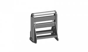
| RDT 1000/520 | Robust roller conveyor with coolant gutter. Width of cylinders 520 mm, length 1000 mm, 3 rollers, it is possible to put them for RDP or RDZ, load capacity 2100 kg/m. | O | |
| RDT 2000/520 | Robust roller conveyor with coolant gutter. Length 2000 mm, width of cylinders 520 mm, 5 rollers, load capacity 2100 kg/m. | O | |
| RBR 280/520 | Side support fixed cylinder, height 280 mm, diameter 67 mm including support. Moun-ted to the conveyor RDT/RDM 2000. Impossible assemble on VD rollertables. | O | |
| RBRS 280 | Side movable cylinder with own frame and fixation, it is available only with RBR. Hei-ght 280 mm, diameter 67 mm. Impossible assemble on VD rollertables. | O | |
| VZM-520 | Hydraulic operated lifting motorized cylinder, width 520 mm.VZM is designed to lift the material using hydraulic short-stroke cylinder above the level of other rollers on the conveyor. After lifting the VZM can move the material forwards or backwards by electric motor. VZM is installed instead of 2 original passive cylinders. VZM is operated independently with own control panel. VZM works only with RDT. | O | |
 | 500-RDH | Independent movable cylinder, adjustable height, capacity 1000kg. | O |
| V-520 | Additional roller placed between rollers of RDT table. Price for 1 pc. Impossible to install on VD roller conveyors. | O |
Tech. data NO241 are valid on 1.1.2024. Producer has the right to make changes of technical data.
Values contained on this page are only for information purposes. This information is not an offer and is not a public promise. This indicative offer does not give right to close a contract. The only guiding document for the contract is a valid price list.
or send inquiry!