


 540 HORIZONT X-CNC / Horizont

| mm | 0° | 45° | 60° | -45° | -60° |  |
 |
|---|---|---|---|---|---|---|---|
 |
540 | 510 | 350 | 510 | 310 | 750x450 | |
 |
750x490 | 510x490 | 350x490 | 510x490 | 310x490 | 750x450 |
 |
 |
 |
 |
 |
|---|---|---|---|---|
| 3x400V | 5,5 | 15-150 | 6880x41x1,3 | 3875 |
| Lmin | Lmax | Bmin | Bmax | Hmin | Hmax | V |
|---|---|---|---|---|---|---|
| 3480 | 4696 | 6013 | 6013 | 2400 | 2510 | 810 |
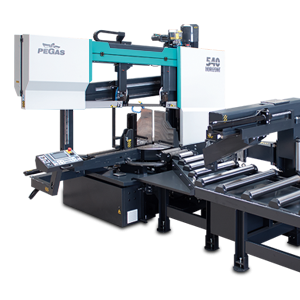
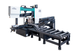
- Highly productive, automatic dual column band saw with multiple material feeding
- The saw is designed for cutting material in both straight and angular cuts, angular cuts adjustable 150°left, 90°perpendicular, 30°right (+/- 60 degrees).
- The saw is designed for cutting bars of solid material and profiles.
- Saw is used in series production in industrial plants. The saw is designed for cutting straight bars of steel material.
Control system:
- The machine is equipped with programmable PLC SIEMENS SIMATIC S7-1500. The saw blade drive and arm movement are completely controlled by SIEMENS technology.
- The colour touch screen HMI SIEMENS TP 700 COMFORT allows easy communication with the machine operator. It shows working states such as blade speed, cutting feed and the status of individual working movements.
- Display size 7´ (93 mm x 153 mm)
- The saw allows you to work with two modes:
- SEMI-AUTOMATIC (MANUAL) MODE: The saw immediately cuts the material in semi-automatic mode. The operator uses the saw's feeder to manipulate the material to be cut and to accurately move the material into the cut zone. The movement of the feeder is realized by manual buttons or by the GTO function. After starting the GTO function, the operator enters the position of the feeder and pressing the START GTO button moves the feeder to the entered position.
- AUTOMATIC MODE: The feeder feeds the cut blank based on the set program. The operator sets the cutting program and the saw then executes these programs. The operator can store up to 100 programs. One program includes complete cutting settings: blade speed, cutting feed value, cutting bar height setting, bar length setting and number of cuts. The length and number can be set in 20 lines. The saw automatically feeds the different lengths entered.
- The regulation of the cutting feed is realized by the control system using a servo driver, servomotor, ball screw and a pre-tensioned nut located on the saw arm. This achieves a very precise cutting feed. The saw operator enters the desired cutting feed (mm/minute) into the program and the saw accurately adjusts this feed.
- Two basic modes of automatic system regulation (ASR): ARP and RZP.
o RZP = Zone Control. The system allows the optimum cutting feed and saw blade speed to be set in 5 zones of the material to be cut, depending on the position of the blade.
o ARP = Automatic cut regulation system depending on the cutting resistance of the material or the saw blade dullness. The system offers two basic ARP modes: BIMETAL and CARBIDE.
- RTO function to automatically set the desired arm rotation position.
- The control panel is located on the console in a safe position. The control panel includes a digital display of the saw control system and a high quality foil keypad. The keypad is used to control the basic movements of the saw (movement of the arm, vice, turntable and feeder) and to start the saw's working cycle. The control panel is also equipped with a safety button to stop the saw.
- Safety module with self-diagnosis.
- 24 V control
Construction:
- The band saw has a robust design to withstand extreme stresses in production conditions. All machine components are designed and optimized to minimize vibrations and allow maximum cutting performance of the machine.
- Saw blade speed range 15 – 150 m/min.
- The saw arm moves via 2 linear guide rails with 4 trolleys with pre-tensioned ball bearing. The linear guide is mounted on sturdy columns.
- The arm is a robust weldment and is designed to ensure the necessary rigidity and cutting accuracy
- Arm movement by linear guide, ball screw, preloaded nut, worm gearbox and servo drive.
- The saw blade is guided on robust cast iron pulleys.
- WRS - Reinforcement of pulley mounting - drive pulley mounted directly on the output shaft of the gearbox. The pulley is supported on both sides by a bearing seat =minimizing the load on the shaft seat. The tension pulley is held/tensioned by two hydraulic cylinders at both ends of the centre pin =significant reduction of stress and extension of the life of the bearing. The tension pulley mounting is with zero play=conical bearings secured by KM nut.
- The arm uses a metering system to evaluate the position of the arm above the material. The working positions of the arm (upper and lower) are set numerically by the saw operator in the cutting program
- The saw uses an absolute rotary encoder to determine the position = no need to reference the position when the machine is switched on.
- The lower position is determined by an adjustable stop and a microswitch. The lower working position of the arm can also be entered directly into the saw control system.
- Main vise with split clamp for fixing the workpiece before and after the cut (straight cuts). The clamps ensure secure clamping of the material.
- Movement of the clamp of the main vise in the rigid steel guide by means of a long-stroke hydraulic cylinder.
- Two robust vise support clamps
- Control valve for vise pressure adjustment, pressure indication on pressure gauge
- The very rigid feeder moves by 2 linear guide rails.
- Feed step 2000 mm, multiple feed (max. length 19 999 mm)
- Feeder movement by linear guide, ball screw, preloaded nut, toothed belt transmission and servo drive.
- Precise positioning of the feeder is handled automatically by the SIEMENS servo driver, including acceleration and deceleration of the feeder before the target position. An incremental rotary encoder for indicating the position of the feeder is included in the servomotor.
- The saw operator manually selects one of five feeder speeds depending on the weight and accuracy of the material being fed.
- Material indication in the feeder: an optical sensor indicates that there is material in the feeder. If there is no material in the feeder, the saw finishes feeding the rest of the bar and waits for the next bar to be inserted.
- A roller conveyor supporting the fed material along its entire length passes through the saw.
- The feeding vise is a robust steel weldment. The jaws ensure secure clamping of the material.
- Movement of the jaws of the feeding vise along two rails of the linear guideway, using hydraulic cylinders. One jaw is long stroke hydraulic cylinder. The other jaw is short stroke. Short-stroke jaw = non-contact reverse motion of the feeder. Advantage when feeding crooked material.
- GTO function (go to position).
- The saw allows two basic feeding modes:
o NORMAL: the feeder moves between the zero position and the position of the specified feed length.
o INCREMENTAL: the feeder moves to the limit position, clamps the bar and feeds it sequentially into the cut.
- Feeder movement modes:
o CONTINUAL: optimal for cutting longer bars
o STEP BY STEP: requires cooperation with the machine operator when taking short pieces. Each step of the program must be confirmed by the machine operator
- CMU mode: opening of the cutting zone on the feeder side for non-contact movement of the saw blade to the upper position. It is used especially when using carbide blades
- The turntable is a robust weldment. Rotary table for angle cuts with machined base guide surface. The rotary table adds a large space for supporting the material and clamping it precisely. Rotation of the angle cutting table by means of a hydraulic cylinder and a linear guide, driven by gear and rack.
- Angle adjustment control:
o Rotation via the button to the desired angle (fast-shift / slow-shift)
o Using the RTO (rotate to position) function with automatic adjustment of the desired arm rotation position
- Automatic rotation after activation of the cutting program
- Hydraulic position "lock"
- Turntable angle displayed on the Siemens control panel display. Indication of set angle by incremental sensor and magnetic tape.
- Optimisation of the chip movement to the chip box or chip conveyor, which is offered as an accessory
- Blade guidance in guides with hardmetal plates, bearings and on cast iron pulleys. Adjustable guides with zero cutting clearance, preloaded by plate springs.
- Robust flange with drive shaft mounting via roller bearing.
- The inclination of the saw blade against the plane of the vise is 7 degrees. This ensures higher performance when cutting profiles and bundles and at the same time increases the life of the saw blade
- The saw has a guide on the drive side mounted on a fixed beam. On the tensioning side, the guide is mounted on a sliding beam.
- Blade guide beam adjustable over the entire working range. The movement of the guide is linked to the movement of the vice clamp. It is therefore not necessary to manually adjust its position.
- The guide beam moves by means of a linear guide (2 rails, 3 trolleys) with high load capacity.
- A new way of mounting the guides - a solution with a regulated spacer.
- BGT-S - mechanical pressure of the saw blade in the guides by means of disc springs.
- The space between the saw blade guide and the pulley is provided with a cover to protect the operator from the moving saw blade. The covers also protect the surrounding area from falling chips and cooling emulsion.
- Automatic Indication of correct saw blade tension by means of a pressure sensor.
- Cleaning brush passively driven by a pulley in the basic version, electric motor as optional.
- Cooling system for cutting emulsion, fed into the blade guides and directly into the cutting channel using the flexible LocLine system.
- Robust base with chip tray. The base is designed for handling the saw with a crane.
- Microswitches for opening pulley covers.
- Hydraulic unit located outside the base - better cooling and access. The hydraulic unit controls the functions of the saw: opening and closing the main vice and feeder vice, rotating the turntable for angle cuts and fixing the turntable in the set rotation. The hydraulic oil pump is located outside the oil tank.
- Two rollers for supporting the cut material. Retractable via linear guide. Positioning on the output side.
- Cover bodywork that covers the movements of the rear of the arm. The body minimises the risk of injury and contamination of the saw's surroundings with chips and cutting emulsion.
- A safety optical barrier ensures operator protection throughout the entire range of movement of the turntable, arm and feeder. Optical line along the entire length of the saw at the operator's position.
- Chip rinsing pistol
- LED strip for work area lighting.
Basic equipment of the machine:
- Saw blade
- Tool set for routine machine maintenance.
- Operating instructions in electronic form on CD.
| Code | Description | Type | |
|---|---|---|---|
| SIEMENS HMI 7" | Controling system SIEMENS with display 7". | ST | |
| 540-HMI+FK | HMI = colour control touch screen. FK=foil keyboard with basic movements | ST | |
| PCP | One year subscription for external machine programming (for Siemens control system) using www server. | O | |
| BLUEBOX | Router for remote saw service. | OP | |
| ZAPSI | Industry 4.0, Connection to bandsaw monitoring and evaluation of machine efficiency, operation, production, and energy consumption. | OP | |
| 540-OPS | Protective cover for control panel. Hinged plate made of thin sheet metal. | O | |
| 540-OPE | Control panel on a freestanding external console. | OP | |
| F | Motor and frequency converter for a fluent change of the circumferential speed of the blade. | ST | |
| 540-DRIVE | Motor (5,5 kW) + bevel gearbox | ST | |
| 540-HM-DRIVE | More powerfull motor (7,5 kW) + bevel gearbox optimal for full use of the carbide (HM) saw blade. Calculated as assesories | OP | |
| WRS | Reinforcement of wheel mounting. The tensioner wheel shaft is reinforced with an additional hydraulic cylinder, the drive wheel shaft is reinforced with a bearing and a beam mounted to the frame. | ST | |
| NPH-2 | Hydraulic band tension with two hydraulic cylinders located on both sides of blade tension wheel. | ST | |
| BCA-7 | Slope of the saw blade (frame) 7 degrees. Optimal solution for cutting profiles and bundles, neutral solution for cutting solid bars. | ST | |
| IRP | Down shift speed indication value on the display of control system ( mm/min ) | ST | |
| 540-BSB SERVO | Movement of bow by linear guides, ball screw and servo motor. | ST | |
| 540-BSF SERVO | Movement of feeder by linear guides, ball screw and servo motor. | ST | |
| AFS | Automatic regulation of the feeder speed depending on the weight of the transported material. | ST | |
| PEGAS ASR | ASR = Automatic cutting feed regulation based on set parameters. | ST | |
| CDC | Basic library with cutting parameters, operator inputs the material informations (dimensions, type, quality) Automatical setting of cutting parameters. Operator set only information about quality and dimension of material. | ST | |
| 540-KKR | Blade deviation monitor. | OP | |
| 540-IMB | Indication of saw blade movement. If the saw blade jams, the drive pulley rotates and the tensioner pulley stands. The function protects the saw blade by stopping the arm from moving into the cut | OP | |
| HPV | Solution of moving guides of band together with jaws of the vice. | ST | |
| PCK | Cleaning brush of blade, driven passively (driven by pulley). | ST | |
| 540-H-ECK | Cleaning brush of blade driven actively by motor. D=125 mm. Belt drive, 790 RPM. | OP | |
| LED | Lighting of workink space. | ST | |
| 540-PUH+PUD+RTO | PUH = Hydraulic turning of the turntable, including hydraulic position fixation. PUD = Angle indication-digital. Shows the set angle on the digital display. RTO = automatic rotation to set angle | ST | |
| 540-PVZ | Supportin cylinder , situated on the base of the saw on the linear feeding - outpud (right) side. | ST | |
| 540-PVP | Supportin cylinder , situated on the base of the saw on the linear feeding - Inpout (left) side. | ST | |
| 540-CLT | Automatic lubrication of the turntable movement by the modified MINI-LUBE systém | OP | |
| 540-CSE | Centre section of the turntable (cut-through segment). CSE = central segment. | O | |
| 540-GPP | Support plate of the cut material before cutting. Only for cutting perpendicular cuts, mounted instead of the PVP support roller. | O | |
| 540-GPZ | Support plate for the cut material behind the cut. Only for cutting perpendicular cuts, mounted instead of the PVZ support roller. | O | |
| RTS-A | Regulation press of vice – set of 2 pcs for bothvices. | ST | |
| OCP | Rebounding jaw of feeder vice. Controled by short-stroke cylinder, placed on linear leading. | ST | |
| 540-H-ATB | Automatic material feed precisely into the cutting zone. | OP | |
| 540-VTT | Universal pusher chip ejector without centre tube, included 1 Pc of BOX-TRI-L2 | OP | |
| 540-VTT-D | Optional chip conveyor extension for transportation of chips. Available only together with 540-VTT. | OP | |
| 540-H-LSG | Optical protection fence that protects the machine operator from dangerous movements of the saw components in the automatic cycle. | ST | |
| 540-H-LSG-Z | LSG-Z is an optical protective fence placed behind the saw. | OP | |
| 540-HP1 | Collision-free long-stroke top pressure. Located on the pivoting part of the saw. Movement of the jaw on 2 rails and 4 carriages of linear guideway. Transverse feed: loose fit on linear guide, manual position adjustment. **not applicable for CNC angle cutting | OP | |
| 540-HP2 | Collision-free long-stroke vertical clamp. Positioned on an attachment frame on the saw. Movement of the jaw on 2 rails and 4 carriages of linear guideway. Designed for cutting bundles, a saw fitted with this device can cut 45 deg. angled cuts with limited turntable rotation to the left only. Easy disassembly, transport by crane. | OP | |
| 540-HP3 | Collision-free long-stroke top pressure. Positioned on the feeder. Movement of the jaw on 2 rails and 4 carriages of linear guideway. Support frame with 180° rotation to a position that does not jam during angular cuts of individual bars . | OP | |
| MINI LUBE 41 | Wasteless lubricating system – 2 pumps, for blade 41 mm. Instead of emulsion cooling, specially for cutting profiles and non-ferrous metals, necessary supply of pressed air 6 Atm. | O | |
| LASER LINE | Laser indicator of cut position. | O | |
| 540-H-SET M42 | Set of 10 blades in SPECTRA M42 quality – customer chooses blade's TPI. Blade specs: 6880x41x1,3 | O | |
| 540-SET M51 | Set of 10 blades in DURATEC M51 quality – customer chooses blade's TPI. Blade specs: 6880x41x1,3 | O | |
| 540-H-NAV | Instruction Manual – printed version. | O | |
| PAL4 | Packing on the palette 1,5 m x 3,5 m. | O | |
| 540 RDL 1000 | Left side connecting roller conveyor. Provides connection of the saw with RDT, RDM. Length 1000 mm, width 620 mm, 5 rollers, load capacity 850 kg/m. Includes function of automatic shifting of 3 support rollers when the saw is angled. Placement of 3 rollers on linear guide. | O | |
| 540-RBR-RDR/L | Side roller with bracket for mounting on roller track RDR/RDL | O | |
| RDT 1000/800 | Robust roller conveyor with coolant gutter. Length 1000 mm, width of cylinders 800 mm, 3 rollers, load capacity 2700 kg/m. | O | |
| RDT 2000/800 | Robust roller conveyor with coolant gutter. Length 2000 mm, width of cylinders 800 mm, 5 rollers, load capacity 2700 kg/m. | O | |
| SYNC-2 | Synchronisation of the saw feeder movement with the roller rotation of the RDM powered conveyor in the automatic cycle. Additionally, it is possible to move the feeder synchronously with the vice clamp closed and the RDM track rollers even with manual operation | OP | |
| RDM 2000/800 | Input or output robust motorised roller table. Powered by electric motor, worm gearbox and inverter. Width 800 mm, length 2000 mm. Load capacity 2700 kg/m. For automatic CNC saws can only be used with SYNC-2 accessories | OP | |
| RDML 2000/800 | Input or output robust roller conveyor with driven rollers. Driving from RDM throught chain. (RDM-L does not work without RDM conveyor). Width of cylinders 800 mm, length 2000 mm. Load capacity 2700 kg/m. | OP | |
| VZM-800 | Hydraulic operated lifting motorized cylinder, width 800 mm. VZM is designed to lift the material using hydraulic short-stroke cylinder above the level of other rollers on the conveyor. After lifting the VZM can move the material forwards or backwards by electric motor. VZM is installed instead of 2 original passive cylinders. VZM is operated independently with own control panel. VZM works only with RDT 2000. | OP | |
| 500x750-RBR | Side support fixed cylinder, height 280 mm, diameter 92 mm with its own frame, mounted to roller tables RDT. | O | |
| 500x750-RBRS | Side adjustable roller with its own steel frame, and with the movable leading 800 mm, fixed by 2 pcs of T-nuts. Height 280 mm, diameter 92 mm. | O | |
| RDH-800 | Independent movable cylinder, adjustable height, capacity 700 kg.Width of roller 800mm. | O | |
| V-800 | Additional roller placed between rollers of RDT table. Price for 1 pc. Impossible to install on VD roller conveyors. | O | |
| RDT-XY1-800 | Roller table setup (with one motorised VZM-800). The setup has total Length 7500 mm. In this option is included 4 powered cross-conveyors with Length of 4000 mm. The flow of material is one way, manual control. Max. weight of material transferred per one segment: 1000 kg.For connection to the saw it is necessary to order RDR / RDL | O |
Tech. data NO241 are valid on 1.1.2024. Producer has the right to make changes of technical data.
Values contained on this page are only for information purposes. This information is not an offer and is not a public promise. This indicative offer does not give right to close a contract. The only guiding document for the contract is a valid price list.
or send inquiry!